Julian Schwinger Ph.D.
Julian Schwinger Ph.D.
The Nobel Prize in Physics 1965
National Medal of Science – Physical Sciences 1964
Nobel co-recipients Sin-Itiro Tomonaga, Richard P. Feynman
Biography
Patents
Nat’l Medal – Physical Sciences
Patents
| Publication: | 1/2 |
| Publication No: | US 2731602 A |
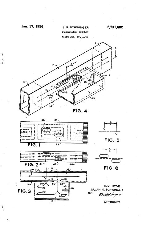
| Title: | Directional coupler |
| Publication Type: | Grant |
| Publication Date: | Jan 17, 1956 |
| Filing Date: | Jan 10, 1946 |
| Inventors: | Julian S Schwinger |
| Assignee: | Julian S Schwinger |
| Abstract: | This invention relates to wave guides and more particularly to directional couplers used in conjunction with wave guides.
(a) Wave guide directional couplers possess properties which make them useful for power monitoring purposes and for impedance measuring or matching. They are used to provide test points in ultra high frequency transmission systems, at which transmitter power may be measured, or at which signals of known amplitude may be introduced in order to measure receiver sensitivity, in a manner that is relatively free from standing Waves in the guide. Wave guide directional couplers may also be used to aid in determining standing wave ratio in a wave guide, a knowledge of which is valuable in providing correct termination for the wave guide. |
| Representative Figure: |  |
| Family | None |
| Details | Google Patents |
| Publication: | 2/2 |
| Publication No: | US 2643295 A |
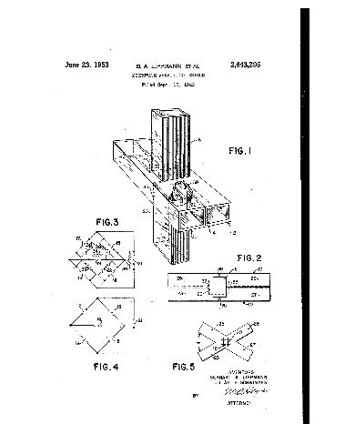
| Title: | Microwave wheatstone bridge |
| Publication Type: | Grant |
| Publication Date: | Jun 23, 1953 |
| Filing Date: | Sep 13, 1946 |
| Inventors: | Bernard A. Lippman, Julian S Schwinger |
| Assignee: | US Navy |
| Abstract: | This invention relates in general to microwave bridge circuits and more particularly to a guided wave transmission line junction exhibiting the properties of a Wheatstone bridge. (a) The Wheatstone bridge is a conventional means for accurately determining resistance. It is very useful in making such measurements at low frequencies and with direct currents. (b) Circuit constants at radio frequency are generally determined by some form of substitution in a bridge circuit. A typical procedure includes first balancing the system as well as the standard impedances in the unknown arm of a bridge, then removing the unknown impedance and readjusting a standard impedance to restore balance. The change in the resistance and reactance components of the standard then indicates the corresponding components of the unknown. This method provides very accurate means of determining the unknown impedance except when the unknown impedance has a high Q. Under such conditions it is necessary to determine the exact equivalent of the standard impedance. Such procedures have been impractical with circuits employing waveguides. (c) It is thus an object of this invention to provide a means of joining a plurality of waveguides to form effectively a Wheatstone bridge circuit. (d) Another object of this invention is to provide a waveguide bridge for determining directly the impedance of an unknown element. |
| Representative Figure: |  |
| Family | None |
| Details | Google Patents |
